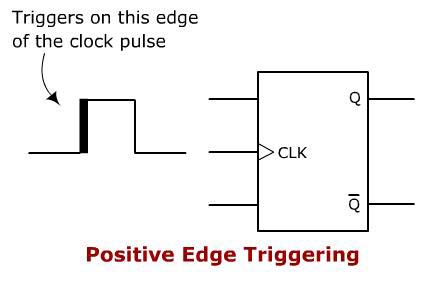

Return to Digital / Logic / Processing menu. In general it has one clock input pin (CLK), two data input pins (J and K), and two output pins (Q and Q) as shown in Figure 1. Previous page Next pageįPGA programming Embedded systems How a computer works Logic circuit design basics Logic / circuit design guidelines The two signals will be seeking to either set or reset the circuit, and the length of time that Q is high will be dependent upon the phase difference between the two signals. One could be as a phase detector in a phase locked loop. This type of circuit may have a number of applications in logic circuit design. Additionally attention should be paid to the earthing of the logic devices does not introduce any problems. To ensure this does not happen, the supply should be well decoupled, and in addition to this the wiring should be routed in such a way that no stray pulses should be picked up. These may be very difficult to track or see using an oscilloscope, especially if they are random in nature. Even very short but fast pulses will be sufficient to trigger the circuit. Note the use of the small > inside the flip-flop logic symbol near the clock input. N74F50109N datasheet Philips Synchronizing dual J-K positive edge-triggered flip-flop with metastable immune characteristics. The logic symbol for a D flip-flop with positive-edge triggering is shown in Fig.

The very nature that this logic circuit is edge triggered means that great care must be taken to ensure that no stray edges are able to spuriously trigger the circuit. ( D flip-flop with Positive-edge-triggered and Negative-edge-triggered clock signal) D flip-flop with Positive-edge-triggered and Negative-edge-triggered clock signal.

When using this logic circuit it is necessary to adopt a few precautions otherwise there can be problems that may be difficult to see and solve. A low to high on CK2 then sets Q1 to low. When there is a low to high transition on the set input to the circuit on CK1 this sets the Q1 output to high.


 0 kommentar(er)
